The options available in a Coil feature depend on the chosen
Conductor model:
In the Homogenized multi-turn case, the coil type determines how the direction of the wires constituting the coil is specified, as well as the method used to compute the average length and the average cross-section area of the domain or boundary. The coil length and coil area are used to compute lumped variables, such as the induced voltage or the total resistance.
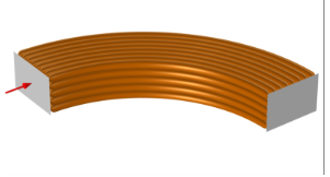
In a linear coil, the wires are straight and parallel. To specify the direction of the wires, use the default
Coil Geometry subnode to select a straight edge or a group of collinear straight edges along the entire length of the coil. The coil direction is taken to be the tangential vector to the edges (shown in the Graphics window with a red arrow), while the length of the wires in the domain is the total length of the edges. If the length of the edges does not correspond to the length of the domain, select the
Override length of the edges check box and specify the correct length. For domain features, the average domain cross-section area is computed from the domain volume and the length. To specify another cross-section area, select the
Override domain area check box and specify the correct area.
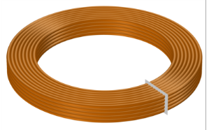
In a circular coil, the wires are wound in circles around a common axis. To specify the direction of the wires, use the default a
Coil Geometry subnode to select a circular edge or group of edges. The feature will compute the coil axis and the wire directions by analyzing the curvature of the selected edges. The total length of the edges is taken to be the average wire length in the domain, so it is appropriate to select a group of edges close to the average radius of the coil. If the length of the edges does not correspond to the length of the domain, select the
Override length of the edges check box and specify the correct length. For domain features, the average domain cross-section area is computed from the domain volume and the length. To specify another cross-section area, select the
Override domain area check box and specify the correct area.
The geometry analysis algorithm can determine the axis and direction only if there is a geometry in the model. If the model does not have a geometry, for example when using imported meshes, use the alternative analysis method by selecting the Use robust geometry analysis method check box. This method can be used even without a geometry, but it requires that the selected edges form a complete circle to work correctly. If neither the default method nor the alternative method work, an alternative is to set the
Coil type to
User defined and manually specify the direction of the wires using a
Cylindrical System.
In a numeric coil, the path of the wires in the coil is computed numerically in an additional study step during the solution. This allows the modeling of coils with complex shapes. To set up the numerical analysis computation of the current flow in a coil, additional information on the coil geometry must be provided by means of the default
Geometry Analysis subnode and the boundary conditions under it.
By default, the Input (for Geometry Analysis) boundary condition is available under the
Geometry Analysis subnode. For open coils (whose ends are on exterior boundaries), apply this condition on the input boundary, that is, the boundary at which the wires enter the coil domain. Right-click the Geometry Analysis node, add an
Output (for Geometry Analysis) subnode, and apply it on the exterior boundary where the wires exit the domain.
To complete the set up, add a Coil Geometry Analysis study step to the study, before the main study step.
In a user-defined coil, the current flow (the direction of the wires) can be entered as an arbitrary vector field in the
User-Defined Coil Geometry subnode. The vector field entered can be an analytical expression or the solution of another physics (for instance, the vector field computed by a
Curvilinear Coordinates interface). In order for the magnetic problem to have a solution, the vector field must be as much as possible divergence-free, meaning that the current flow cannot have sources or sinks within the simulation domain nor can it originate from interior boundaries. In practice, this means that the current flow must either be terminated on exterior boundaries, or it must be closed in a loop.
The setup of the Coil when using the Single conductor model is similar to the setup required for the Homogenized Multi-Turn Model — Numeric Coil Type case, the only difference being that the Coil Geometry Analysis study step will compute the physical current flow, instead of the direction of the wires. Refer to that section for more information.
The 3D Single-Turn Coil feature was available in
The Magnetic Fields Interface in previous versions of COMSOL Multiphysics. This feature is obsolete — the recommended approach to model the same physical system is to use a
Coil feature with the
Single conductor model, or
The Magnetic and Electric Fields Interface.
The excitation is applied by means of specialized subnodes: a Boundary Feed subnode applies constraints on the coil potential to an external boundary, while a
Ground subnode enforces the coil potential to be zero on the selected boundaries.
A Gap Feed subnode models a thin gap in the conductive domain across which a difference of potential or a current is applied. This feature should be applied on interior boundaries to the conductive domain and is useful for modeling closed loops.