You are viewing the documentation for an older COMSOL version. The latest version is
available here
.
Tutorial Example: Modeling a 3D Inductor
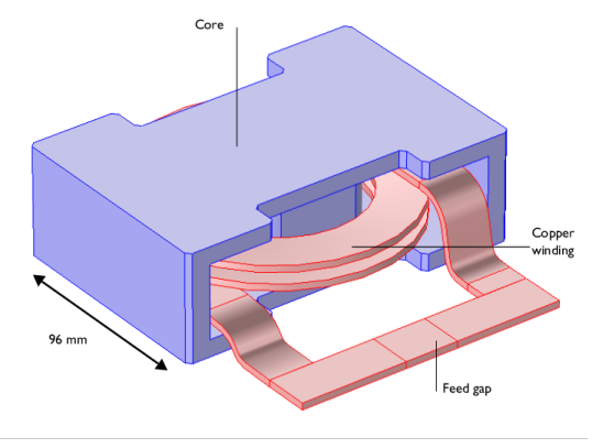
Inductors are used in many applications for low-pass filtering or for impedance matching of predominantly capacitive loads. They are used in a wide frequency range from near static up to several MHz. An inductor usually has a magnetic core to increase the inductance while keeping its size small. The magnetic core also reduces the electromagnetic interference with other devices as the magnetic flux tends to stay within it. Because there are only crude analytical or empirical formulas available to calculate impedances, computer simulations or measurements are necessary during the design stage. In general, inductor modeling is more complex than modeling resistors and capacitors but similar principles apply. Using an external CAD software to design and draw the model, the geometry is imported into the AC/DC Module for static and frequency domain analysis. The inductor geometry is shown in
Figure 7
.
Figure 7:
The inductor geometry.
First a magnetostatic simulation is performed to get the DC inductance. At low frequencies capacitive effects are negligible. A relevant equivalent circuit model is an ideal inductor in a series with an ideal resistor. The inductance and the resistance are both computed in the magnetostatic simulation. At a high frequency, capacitive effects become significant. The equivalent circuit model involves connecting an ideal capacitor in parallel with the DC circuit. The circuit parameters are obtained by analyzing the frequency dependent impedance obtained from a frequency domain simulation. In this tutorial, the AC analysis is done up to the point when the frequency dependent impedance is computed.
These step-by-step instructions guide you through the detailed modeling of an inductor in 3D. The module also has a physics interface to model electrical circuits, which is detailed in the magnetostatic part of this model. The first step is to perform a DC simulation.