Thickness and Offset
Use the Thickness and Offset node to define the thickness for the different parts of the shell structure. In addition to the default Thickness and Offset node always present in the interface, you can add more Thickness and Offset nodes if needed.
If the actual shell midsurface is not on the selected boundaries, you can also prescribe an offset in the direction of the surface normal. The offset is defined as positive if the shell midsurface is displaced from the meshed boundary in the direction of the positive shell normal.
Thickness and Offset
Enter a value for the Thickness d of the selected boundaries. The default is 0.01 m. The thickness can be variable if an expression is used.
Select an option from the Offset definition list — No offset, Relative offset, or Physical offset.
For No offset, the modeled boundary coincides with the shell midsurface.
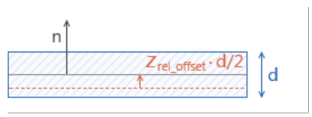
For Relative offset, enter a value or expression in the zrel_offset field for the offset as the ratio between the offset distance and half the shell thickness. A value of +1 means that the actual shell bottom surface is located on the meshed boundary, and a value of -1 means that the shell top surface is located on the meshed boundary.]
Figure 5-6: Meshed boundary indicated in red. The vector n indicates the positive orientation of the shell normal.
For Physical offset, enter a value or expression in the zoffset field for the actual distance from the meshed boundary to the shell midsurface.
Figure 5-7: Meshed boundary indicated in red. The vector n indicates the positive orientation of the shell normal.
Thickness and offset settings specified on this node are not applicable for a Layered Linear Elastic Material node as this information is provided on Layered Material, and Layered Material Link nodes.
Location in User Interface
Context Menus
Shell>Thickness and Offset
Plate>Thickness and Offset
Ribbon
Physics tab with Shell selected:
Boundaries>Shell>Thickness and Offset
Physics tab with Plate selected:
Domains>Plate>Thickness and Offset