|
|
|
2
|
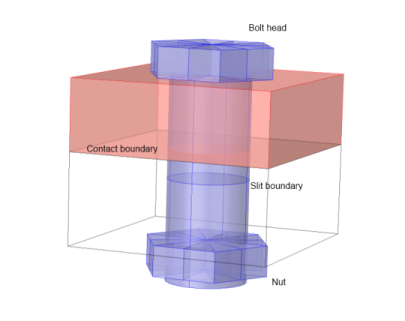
Make sure that there is at least one internal boundary perpendicular to the bolt axis somewhere in the shank. In the following, this boundary is referred to as the slit boundary (Figure 2-20). The slit boundary can be composed of several boundaries in the geometry.
|
|
3
|
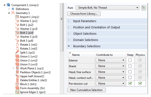
If you are using bolts from the Part Libraries, a slit boundary is predefined, and has the selection name Pretension cut. In order to make this boundary selection visible from the physics interface, select its Keep check box in the Boundary Selections section of the settings for the part instance (Figure 2-21).
|
|
5
|
Add a Bolt Pretension node, in which the pretension force or stress is prescribed for a set of bolts with the same data.
|
|
6
|
For each bolt having an identical pretension stress, add a Bolt Selection subnode where the slit boundary is selected.
|
|
|
When a bolt is located in a symmetry plane (so that only half the bolt is modeled), and Automatic symmetry detection is selected in the Bolt Selection node, the given pretension force is interpreted as the force in the whole bolt, not as the force in the modeled half. This makes it possible to use the same Bolt Pretension node for a set of similar bolts where some of them are located in symmetry planes.
|
|
1
|
Run the study step for the mounting simulation. The predefined study type Bolt Pretension is designed for this.
|
|
3
|
Since the pretension degrees of freedom are not solved for in the service load study steps, they must obtain their values from the pretension study step. If the study steps are sequential within the same study, this action is not needed, since the default then is to inherit values from the previous study step. For other cases, go to the Values of Dependent Variables section of the study step, set Values of variables not solved for to User controlled, and then select the pretension study step.
|
|
|
If you use the Bolt Pretension study type for the pretension study step, and any other study type to analyze the service loads, the solvers are automatically set up to handle this. The Bolt Pretension study type is actually a special case of a Stationary study step, with the sole purpose of activating the predeformation degrees of freedom. These degrees of freedom are by default not solved for in any other study type.
You enable or disable the solution of individual degrees of freedom under the Dependent Variables node for a certain study step in the solver sequence. If required, begin by clicking Show Default Solver in the study node or in the Solver Configurations node of the study. Then move to the Dependent Variables node, and in the General section, set Defined by study step to User defined.
You can now go to the node for each predeformation degree of freedom below Dependent Variables and adjust the state of the Solve for this state check box.
For more information, see also Dependent Variables and Studies and Solvers in the COMSOL Multiphysics Reference Manual.
|
|
|
Studies and Solvers in the COMSOL Multiphysics Reference Manual
|
|
|
Prestressed Bolts in a Tube Connection: Application Library path Structural_Mechanics_Module/Contact_and_Friction/tube_connection
|