You are viewing the documentation for an older COMSOL version. The latest version is
available here
.
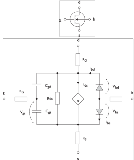
MOSFET Transistors
Figure 4-2
illustrates an equivalent circuit for the n-channel MOSFET transistor. The p-channel MOSFET transistor is treated similarly, but the polarities of the involved voltages are reversed.
Figure 4-2:
A circuit for the MOSFET transistor.
The following equations are used to compute the relations between currents and voltages in the circuit.
There are also several capacitances between the terminals
The model parameters are as follows:
Table 4-2:
MOSFET Transistor Model Parameters
Parameter
Default
Description
C
BD
0 F/m
Bulk-drain zero-bias capacitance
C
GDO
0 F/m
Gate-drain overlap capacitance
C
GSO
0 F/m
Gate-source overlap capacitance
F
C
0.5
Capacitance factor
I
S
1e-13 A
Bulk junction saturation current
K
P
2e-5 A/V
2
Transconductance parameter
L
50e-6 m
Gate length
M
J
0.5
Bulk junction grading coefficient
N
1
Bulk junction ideality factor
P
B
0.75 V
Bulk junction potential
R
B
0
Ω
Bulk resistance
R
D
0
Ω
Drain resistance
R
DS
Inf (
Ω
)
Drain-source resistance
R
G
0
Ω
Gate resistance
R
S
0
Ω
Source resistance
T
NOM
298.15 K
Device temperature
V
TO
0 V
Zero-bias threshold voltage
W
50e-6 m
Gate width
Γ
(
GAMMA
)
1 V
0.5
Bulk threshold parameter
Φ
(
PHI
)
0.5 V
Surface potential
Λ
(
LAMBDA
)
0 1/V
Channel-length modulation