Use the Grating node to treat a boundary as a diffraction grating that can release reflected and transmitted rays of multiple diffraction orders. A
Diffraction Order subnode for reflected and transmitted rays of order
m = 0 is added by default. Change the settings for this default subnode to release rays of a different diffraction order. You can also release rays of multiple diffraction orders from the same boundary by adding more
Diffraction Order subnodes from the from the context menu (right-click the parent node) or from the
Physics toolbar,
Attributes menu.
The Accumulator (Boundary) subnode is also available from the context menu (right-click the parent node) or from the
Physics toolbar,
Attributes menu.
When two or more rays are released from a Grating boundary, one of the released rays uses the same degrees of freedom as the incident ray. The remaining degrees of freedom must be preallocated in memory as secondary rays. The total number of secondary rays that can be released in the model is controlled by the
Maximum number of secondary rays field in the physics interface
Ray Release and Propagation section.
For example, if both reflected and transmitted rays of diffraction orders m = −1,
m = 0, and
m = 1 are released from a boundary, then for every incident ray, a total of five secondary rays are released. If the diffraction order
m = −1 is the first subnode to appear in the Model Builder, then the transmitted ray of order
m = −1 uses the same degree of freedom as the incident ray, and the other rays are secondary rays. If the
Maximum number of secondary rays is
500 and more than
100 rays interact with the grating, then no more secondary rays are emitted and a warning is generated by the solver, indicating that the
Maximum number of secondary rays should be increased.
Select an option from the Rays to release list:
Reflected and transmitted (the default),
Reflected, or
Transmitted. Then enter the a
Grating constant d (SI unit: m). The default is
600 nm.
If the ray power is solved for, the Store total transmitted power and
Store total reflected power check boxes are shown. Select these check boxes to declare auxiliary dependent variables for the total power of all transmitted and reflected diffraction orders, respectively.
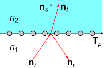
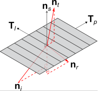
The vectors Tl and
Tp are illustrated in
Figure 3-5, along with typical paths for incident reflected, and transmitted rays.