where ρ is the fluid density (SI unit: kg/m
3),
A is the pipe cross section area (SI unit: m
2) available for flow,
Cp (SI unit: J/(kg·K)) is the heat capacity at constant pressure,
T (SI unit: K) is the temperature.
u is a velocity field. For information about the tangential velocity in pipe flow, see
Theory for the Pipe Flow Interface. Further,
k (SI unit: W/(m·K)) is the thermal conductivity. The second term on the right hand side corresponds to friction heat dissipated due to viscous shear.
Q (SI unit: W/m) represents a general heat source and
Qwall (SI unit: W/m) represents external heat exchange through the pipe wall. Note that the
Qwall term is detailed below.
An additional term Qp can be added to the right-hand side of the equation by enabling the
Pressure Work check box:
In Equation 3-3,
(hZ)eff is an effective value of the heat transfer coefficient
h (SI unit: W/(m
2·K)) times the wall perimeter
Z (SI unit: m) of the pipe.
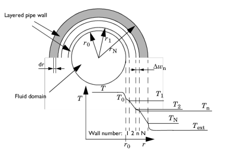
Text (SI unit: K) the external temperature outside of the pipe. See
Figure 3-3.
Qwall appears as a source term in the pipe heat transfer equation,
Equation 3-1.
Text in
Equation 3-3 can be a constant, parameter, expression, or given by a temperature field computed by another physics interface, typically a 3D Heat Transfer interface.
h is automatically calculated through film resistances and wall layers that are added as subnodes; see
Equation 3-17 an on.
If Text is given as the temperature field computed by another 3D Heat Transfer interface, automatic heat transfer coupling is done to the 3D physics side as a line source. The temperature coupling between the pipe and the surrounding domain is implemented as a line heat source in the 3D domain. The source strength is proportional to the temperature difference (
Equation 3-3) between the pipe fluid and the surrounding domain.
In Figure 3-3, consider a short length section
ΔL of , perpendicular to the figure plane. The heat leaving the internal fluid of that segment into the wall is
Here, AQ = ΔL2πr0 (SI unit: m
2) is the area available for heat flux into the wall. For stationary conditions that same amount of heat must travel through any cylindrical shell at radius
r in wall 1 (or any wall).
where (hAQ)eff is an effective conductance:
where Z (SI unit: m) is an average perimeter (circumference), of the pipe, taken over the thickness of the pipe walls. Combine
Equation 3-10 and
Equation 3-14 such a that
For a circular pipe cross sections, this effective hZ in can now be used in
Equation 3-3. Note the reversed sign since
Qwall is the heat added to the pipe from the surroundings. The assumption in the deduction above is
where k is the thermal conductivity of the material, and
Nu is the Nusselt number.
dh is the hydraulic diameter, defined as
The local temperatures in each radial position of the pipe wall (see Figure 3-3) are computed considering the fact that
Equation 3-3 also can be applied for each individual wall layer:
Combining Equation 3-3,
Equation 3-19 and
Equation 3-15 or
Equation 3-16 (depending on pipe shape) for each wall layer explicitly gives each
Tn.
For internal laminar forced convection in fully developed pipe flow, the Nusselt number is a constant that depends on the pipe cross-section. Values are listed in the table below (Ref. 1). The Pipe Flow interface interpolates to find values for width/height ratios not listed. Default settings for film coefficient calculations are “Automatic”, which means that laminar and turbulent correlations are applied according to the
Re number.
Above d is the outside diameter of the pipe and,
β is the fluid’s coefficient of volumetric thermal expansion:

 .
. .
.