|
|
|
|
1
|
|
2
|
Click Done.
|
|
1
|
|
2
|
|
3
|
Click Browse.
|
|
5
|
Click Import.
|
|
1
|
|
2
|
|
3
|
|
1
|
|
2
|
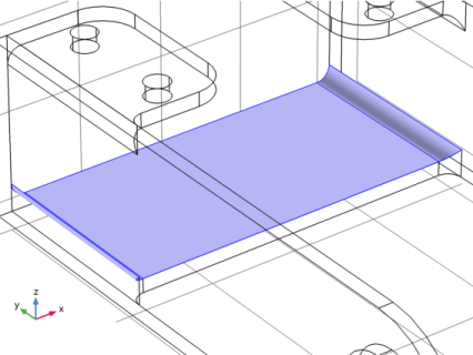
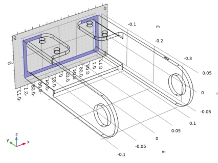
On the object imp1, select Domain 1 only.
|
|
3
|
|
4
|
|
5
|
|
6
|
|
7
|
|
8
|
|
9
|
|
1
|
|
2
|
|
3
|
|
1
|
|
2
|
|
3
|
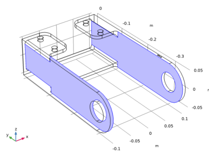
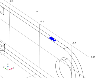
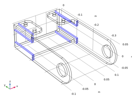
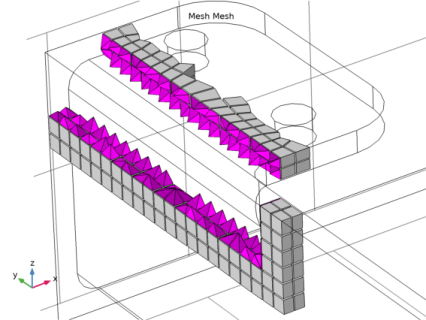
On the object fin, select Edges 123–164 only, by clicking the Select Box button on the Graphics toolbar, and using the mouse to select the edges highlighted below.
 |
|
4
|
|
1
|
|
2
|
|
1
|
|
2
|
|
3
|
|
1
|
|
2
|
|
3
|
Click the Custom button.
|
|
4
|
|
5
|
|
1
|
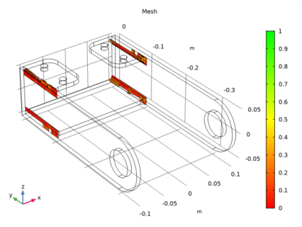
In the Model Builder window, under Component 1 (comp1)>Mesh 1 right-click Swept 1 and choose Distribution.
|
|
2
|
|
3
|
|
4
|
|
5
|
|
6
|
|
7
|
|
1
|
|
2
|
|
3
|
|
4
|
|
5
|
|
6
|
|
7
|
|
8
|
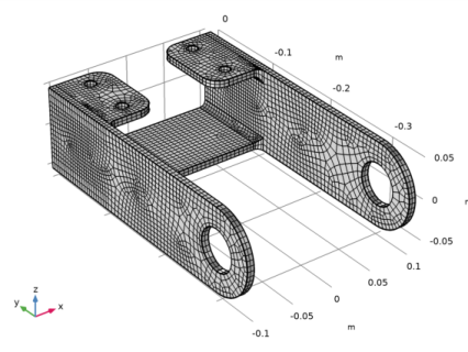
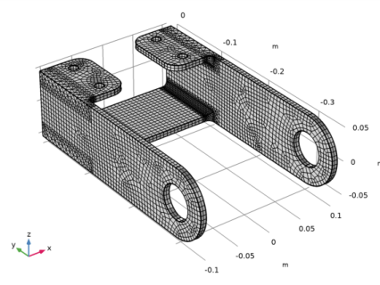
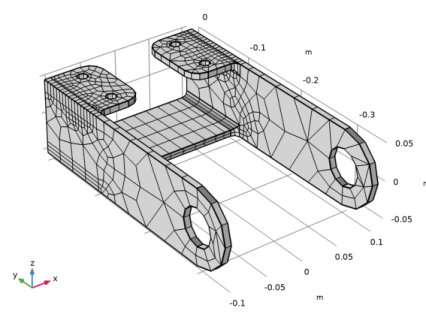
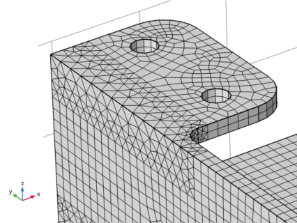
Click the Zoom Box button on the Graphics toolbar and then use the mouse to zoom in to the corner on the bracket displayed below to get a better view of the elements.
 |
|
9
|
|
1
|
In the Model Builder window, under Component 1 (comp1)>Geometry 1 right-click Partition Domains 1 (pard1) and choose Delete.
|
|
2
|
|
3
|
|
4
|
|
5
|
|
6
|
|
1
|
|
2
|
|
3
|
|
4
|
|
5
|
|
6
|
|
1
|
Right-click Component 1 (comp1)>Geometry 1>Work Plane 1 (wp1)>Plane Geometry>Rectangle 1 (r1) and choose Duplicate.
|
|
2
|
|
3
|
|
4
|
|
1
|
|
2
|
|
3
|
|
4
|
|
1
|
Right-click Component 1 (comp1)>Geometry 1>Work Plane 1 (wp1)>Plane Geometry>Rectangle 3 (r3) and choose Duplicate.
|
|
2
|
|
3
|
|
4
|
|
1
|
|
2
|
|
1
|
|
2
|
|
4
|
|
5
|
Locate the Selections of Resulting Entities section. Select the Resulting objects selection check box.
|
|
6
|
|
1
|
|
2
|
Select the object imp1 only.
|
|
3
|
|
4
|
|
5
|
|
1
|
|
2
|
|
3
|
|
1
|
|
2
|
|
3
|
|
5
|
|
1
|
|
2
|
|
3
|
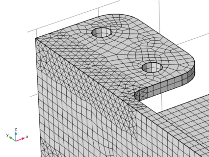
Click the Zoom Box button on the Graphics toolbar and then use the mouse to zoom in to the region below.
 |
|
4
|
|
5
|
|
6
|
|
1
|
|
2
|
|
3
|
|
1
|
|
2
|
|
3
|
|
4
|
|
5
|
Click the Zoom Box button on the Graphics toolbar and then use the mouse to zoom in to the region below.
 |
|
6
|
|
7
|
|
1
|
|
2
|
|
3
|
|
4
|
|
5
|
|
1
|
|
2
|
|
3
|
|
4
|
|
1
|
|
2
|
|
3
|
|
4
|
|
5
|
|
6
|
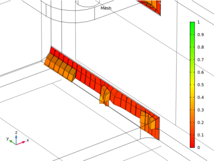
Click the Zoom Box button on the Graphics toolbar and then use the mouse to zoom in to get a better view of the elements.
 |