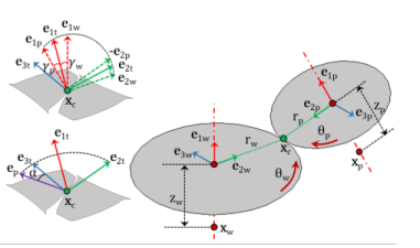
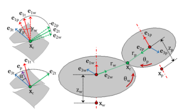
The Gear Pair node connects two spur gears, helical gears, or bevel gears in such a way that at the contact point, they have no relative motion along the line of action. The remaining displacements and rotations of both gears are independent of each other.
The degrees of freedom at the gear pair are θwh and
θpn. They are defined as the rotation of the wheel and pinion about the first axis of their respective local coordinate system.

In a Gear Pair node, you can select any two gears defined for the model. However, for the correct tooth meshing, a set of gears must fulfill the compatibility criteria.
where xc,wh and
xc,pn are the center of rotation of the wheel and pinion, respectively.
where Rwh and
Rpn are the rotation matrices of the wheel and the pinion, respectively. The angles
θwh and
θpn are the rotations of the wheel and pinion about the first axis of their respective local coordinate system.
where Twh and
Tpn are the tooth transformation matrix for the wheel and pinion, respectively.
The gear ratio (gr) of a gear pair is defined as the ratio of angular velocities of the wheel (
ωwh) and the pinion (
ωpn):
The point of contact (xcp) on a gear in its local coordinate system can be defined as:
where θel,
θet, and
θbl are the transmission error (elasticity), transmission error (static), and transmission error (backlash), respectively.
where xcp2,wh and
xcp2,pn are the position of the second contact point and can be defined as:
Here, wpn and
θcl are the working width of the pinion and the relative rotation about center line, respectively. By default, there is no elasticity on a gear pair hence the relative rotation about the center line is zero.
For the case of a line contact model, the second contact force (Fc2) is computed by implementing the line contact constraint in the weak form or by using the penalty factor.
For a line contact model, additional contributions from the contact force Fc2 are added to the forces and moments at the gear centers. These contributions can be defined as:


