Theory for the Reactive Pellet Bed
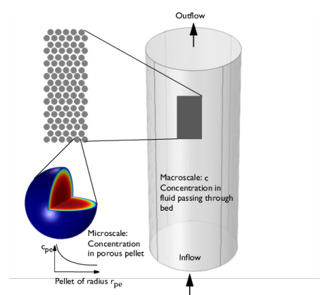
The feature Reactive Pellet Bed, available to users of the Chemical Reaction Engineering Module, adds to the transport of diluted species interface a domain feature that can simulate regions filled with spherical reactive catalyst pellets, as in packed bed reactors. The pellets are simulated with the Extra Dimension technology provided by COMSOL: A 1D, 2D, or 3D domain comprises the bed volume. The extra dimension is the added radial microscale dimension inside each pellet.
Figure 4-3: Schematic showing the macroscale (bed volume) and the microscale (pellet).
The transport and reaction equations inside the pellets is done with an extra dimension feature attached to the 1D, 2D, or 3D physics interfaces, including axisymmetric cases.
The equations inside the spherical pellet are solved as a spherical transport equations on a non-dimensional radial coordinate on the domain 0-1. Different pellet radii and even uneven radius distributions can be used.
The model equations assume spherical particles of a radius rpe. Consider the microscale concentration cpe inside an individual porous pellet or particle, and the macro-concentration c in the packed bed gas volume.
The pellet radius input can be:
The model equation for the bulk (macroscale) species is, for example:
(4-23)
The dependent variable c for each chemical species i represents the interstitial concentration (SI unit: mol/m3), that is, the physical concentration based on unit volume of fluid flowing between the pellets.
εb is the bed porosity (SI unit: 1). It should be noted that the R term on the right hand side is per unit volume of bed, (SI unit: mol/(m3· s)).
Looking inside a pellet: Assuming no concentration variations in the space-angle (θ, ϕ) direction, but only in the radial (r) direction of the spherical particle allows a spherically symmetric reaction-diffusion transport equation inside the pellet. If rdim (SI unit: m) is the spatial radial coordinate in the pellet, and rpe is the pellet radius, the non-dimensional coordinate r=rdim/rpe can defined. The modeling domain on r goes from 0 to 1.
Figure 4-4: Modeling domain in a pellet for a dimensional coordinate (top) and non-dimensional coordinate (bottom).
A shell mole balance across a spherical shell at radius rdim (SI unit: m), and a subsequent variable substitution r = rdim/rpe gives the following governing equation inside the pellet on the domain 0<r<1:
(4-24)
where
N is the number of pellets per unit volume of bed.
Equally as in Equation 4-23, cpe is the interstitial (physical) species concentration in moles/m3 fluid volume element inside the pore channel,
Rpe is the reaction rate in moles/(m3· s) of particle volume. It should be stressed that the user input of R is per unit volume of pellet.
The effective diffusion coefficient in Equation 4-23 and Equation 4-24 depends on the porosity εpe, tortuosity τ, and physical gas diffusivity D in the porous particle generally as
.
The available tortuosity models for porous media are the Millington and Quirk (Ref. 12),
(4-25),
Bruggeman,
(4-26)
and Tortuosity model, where the tortuosity expression is entered as user input:
(4-27)
These are readily used for both gaseous and liquid fluids along with various types of particle shapes. For instance, the first model has been shown to fit mass transport in soil-vapor and soil-moisture wells.
Equation 4-23 can be solved for two types of boundary conditions at the interface between the pellet surface and the fluid in this feature.
Continuous concentrations: assuming that all resistance to mass transfer is within the pellet and no resistance to pellet-fluid mass transfer on bulk fluid side. The concentration in the fluid will thus be equal to that in the pellet pore just at the pellet surface: . This constraint also automatically ensures flux continuity between the pellet system and the free fluid system though so-called reaction forces in the finite element formulation.
Film resistance (mass flux): The flux of mass across the pellet-fluid interface into the pellet is possibly rate determined on the bulk fluid side. The resistance is expressed in terms of a film mass transfer coefficient, hDi, such that:
(4-28),
where Ni, inward is the molar flux from the free fluid into a pellet and has the SI unit moles/(m2· s).
With the film resistance formulation, the free fluid Equation 4-23 needs to be amended for flux continuity so that
(4-29)
where Sb (SI unit: m2/m3) is the specific surface area exposed to the free fluid of the packed bed (not including the inside of the pores).
For the case of randomly packed spherical particles, the specific surface area exposed to the free fluid is (Ref. 3):
(4-30)
The mass transfer coefficient in Equation 4-28 can be computed from the fluid properties and flow characteristics within the porous media. For this, the Sherwood, Sh, number defined as the ratio between the convective mass transfer coefficient and the diffusive mass transfer coefficient is often used:
where L is a characteristic length (for spheres typically the radius) and D the diffusion coefficient in the fluid. From the Sherwood number definition, the mass transfer coefficient can be computed.
Three commonly used empirical expressions for the calculation of the Sherwood number are the Frössling relation (Ref. 4):
(4-31),
which was measured on particles in the size region 1 mm, the Rosner relation (Ref. 5)
(4-32),
and the Garner and Keey relation (Ref. 4)
(4-33),
which was measured for Re numbers greater than 250.
All three depend on the Reynolds, Re, and Schmidt, Sc, numbers. The first describing the fluid flow regime (laminar vs turbulent) and the second, the ratio between the viscous diffusion rate and the molecular (mass) diffusion rate. In the expressions, properties such as velocity, u, dynamic viscosity, μ, and density, ρ, of the fluid are included.