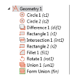
 ..
..|
1
|
Double-click the COMSOL Multiphysics icon to launch COMSOL.
|
|
2
|
|
|
See Toolbars and Keyboard Shortcuts for links and information about all the available toolbars. Also see The COMSOL Desktop Menus and Toolbars.
It is also useful to review Working with Geometric Entities and Creating Named Selections before continuing with these instructions.
|
|
1
|
|
2
|
In the Parameters table, enter, or copy and paste the values in the table below. The Value column automatically displays the Expression value.
|
|
1
|
|
2
|
|
3
|
|
4
|
|
5
|
|
6
|
|
1
|
|
2
|
In the Settings window, under Difference, the Active button is On (
|
|
3
|
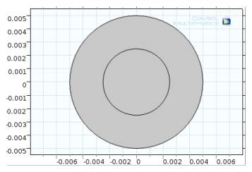
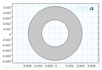
In the Graphics window, click to select object c1 (the larger circle). c1 is added to the Objects to add list.
|
|
4
|
|
5
|
Select the object c2 (the smaller circle). This can be done by clicking it in the Graphics window. Or open the Selection List window (from the Home toolbar, More Windows>Selection List) and right-click c2 (solid) to Add to Selection.
|
|
6
|
Click the Build Selected button (
 |
|
1
|
|
2
|
|
a
|
|
b
|
|
3
|
|
4
|
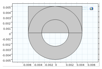
Click the Geometry 1 node. In the Geometry toolbar, from the Booleans and Partitions menu, select Intersection (
|
|
5
|
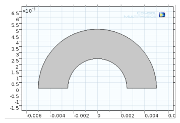
In the Graphics window click to select each object — dif1 (the combined circle) and r1 (the rectangle).
|
|
6
|
|
1
|
|
2
|
|
a
|
|
b
|
|
3
|
|
4
|
Click the Build Selected button (
|
|
1
|
|
2
|
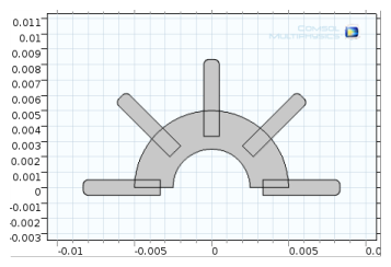
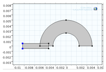
On object r2 (the small rectangle) click each vertex (1 and 4, located in the left-hand corners, highlighted in blue the figure) to add these to the selection lists.
 |
|
3
|
|
4
|
|
1
|
|
2
|
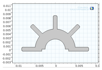
In the Graphics window, click to select object fil1 (the filleted rectangle). It is added to the Input objects list.
|
|
3
|
|
4
|
|
5
|
|
1
|
|
2
|
In the Graphics window click the objects int1, fil1, rot1(1), rot1(2), rot1(3), and rot1(4). These are added to the Input objects section (or click the Select All button (
|
|
3
|
In the Settings window for Union, click to clear the Keep interior boundaries check box to remove the interior boundaries in the union operation. This is good practice if these boundaries do not define separate parts with different materials, for example.
|
|
4
|
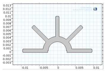
Click the Build All Objects button (
 |
|
1
|
|
2
|
In the Settings window under Parameters, enter these settings in the table. Replace the previous data:.
|
|
3
|
|
4
|
Click the Build All button (
 |