About Frames
The COMSOL Multiphysics software refers to the spatial, material/reference, geometry, and mesh coordinate systems described above as spatial frame, material frame (reference frame), geometry frame, and mesh frame, respectively. Physics can be formulated in the spatial frame or in the material frame, depending on whether it is more convenient to interpret the equations as Eulerian or Lagrangian, respectively. It is not possible to use the geometry and mesh frames and their associated coordinates to formulate physics because they are neither connected to the material nor to the true Euclidean space.
Conceptually, all four frames always exist, but all or some of them can point to the same actual coordinate system. It is the actual coordinate system that decides the names of the independent variables (the coordinate names like xyz or rphi
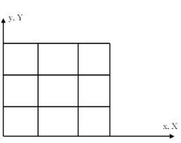
z). Before adding a Moving Mesh or Deformed Geometry interface to a Component, all four frames coincide and use the spatial coordinate names. Also all physics interfaces based on solid mechanics include moving mesh functionality and by default behave much in the same way as a Moving Mesh interface.
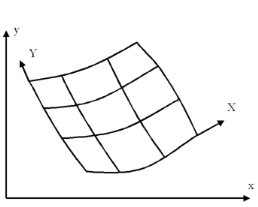
When a Moving Mesh or Solid Mechanics interface is added, the spatial frame is separated from the material frame, which is given a new set of independent variable names (by default capital XYZ or RPHIZ). From this point, Eulerian and Lagrangian formulations behave differently because they, among other things, define derivatives with respect to different sets of independent variables.
The geometry frame and the material frame use the same coordinate system until a Deformed Geometry interface is added. At that point, a new geometry coordinate system is created and given a new set of independent variable names (by default XgYgZg or RgPHIgZg). The new geometry frame refers to the geometry as it is represented by the Geometry Sequence. By inserting a nontrivial transformation from geometry coordinates to material coordinates, the shape of the geometry can be effectively changed without having to create a new mesh. This can be useful as a means of parameterizing the geometry, for example, before performing optimization or sensitivity analysis.
Using Deformed Geometry affects both Eulerian and Lagrangian physics in the same way. The reason is that the Deformed Geometry interface controls the material frame in relation to the geometry frame. Unless there is also a Moving Mesh or Solid Mechanics interface present, the material frame and the spatial frame still refer to the same coordinate system. The three frames refer to three different sets of coordinates only when there is both a Deformed Geometry and some Moving Mesh interface active in the Component.
The geometry frame and the mesh frame coincide until a manual or automatic remeshing operation is performed. At that point, a new mesh is created in the original geometry together with a new set of coordinates (independent variables, typically XmYmZm or RmPHImZm). The original geometry coordinates are mapped and stored together with the new mesh such that any Deformed Geometry interface can still define the material frame relative to the original geometry frame.
To avoid confusion, note that:
The spatial frame is the usual, fixed, global, Euclidean coordinate system with the spatial coordinates (x, y). In the ALE context, the spatial coordinate system as such is fixed, while the spatial coordinates (xy) of each material point and mesh node can be functions of time. Therefore, it is correct to refer to the model as having a moving mesh.
The material frame is a coordinate system that identifies material points by their spatial coordinates (XY) in some — actual or imagined — reference configuration. Think of the material coordinate system as having been printed on the material in the reference configuration such that it follows it during deformation. It is therefore in general curvilinear and cannot be used directly to measure true distances and angles. See also Figure 18-1 and Figure 18-2.
The geometry frame is a coordinate system that identifies points by their spatial coordinates (XgYg) in the original geometry. It is often natural to use the original geometry also as reference state to define material coordinates. Therefore, the geometry frame and material frame usually coincide. The only exception is when a Deformed Geometry interface is used to deform or parameterize the original geometry.
The mesh frame is a coordinate system used internally by the finite element method. It identifies mesh points by their spatial coordinates (XmYm) at the time the mesh was created. The original mesh is always created based on the original geometry. Therefore, the mesh frame coincides with the geometry frame until a new mesh is created in the — then current — deformed configuration.
Figure 18-1: An undeformed mesh. In the reference configuration, which can be the actual configuration at a reference time or a hypothetical state, the spatial frame (x, y) and the material frame (X, Y) coincide.
Figure 18-2: After deformation of the material, the spatial frame (x, y) remains the same, while the material coordinate system (X, Y) has been deformed, following the material. Meanwhile, the material coordinates of each material point remain the same but its spatial coordinates have changed.