Rigid Motion Suppression Boundary Condition
The Rigid Motion Suppression boundary condition is a convenient way to automatically create a set of constraints which are sufficient to inhibit any rigid body modes. The constraints are selected so that no reaction forces are introduced as long as the external loads are in equilibrium.
3D with Translational Degrees of Freedom
In this case, which includes the Solid Mechanics, Multibody Dynamics, Membrane, and Truss interfaces, six degrees of freedom must be constrained. As it is not possible to directly constrain rotations, this must be done by a proper selection of locations and orientations for the constraints.
The following scheme is used:
1
Select three points p1, p2, and p3 that are not located on a common straight line.
2
3
4
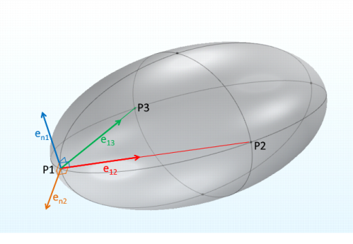
This normal is perpendicular to the line between p1 and p2. Compute a second perpendicular direction, orthogonal to en1.
5
6
Constrain the second point p2 in two directions, so that all possible rotations except around the line e12 are suppressed:
7
Constrain the third point p3 so that the remaining rotation is suppressed:
The body is now constrained against rigid body rotations, while still free to stretch in any direction.
Figure 3-17: Selection of constraint orientations: P1 is fixed, P2 is constrained so that it can only move in the e12 direction, and P3 is constrained in the en1 direction.
3D with Rotational Degrees of Freedom
In the Shell interface, the rigid body suppression is implemented using the translational degrees of freedom in three points, using the same algorithm as above.
In the Beam interface, a single point is constrained in all six degrees of freedom.
2D with Translational Degrees of Freedom
In this case, which includes the Solid Mechanics, Multibody Dynamics, and Truss interfaces, three degrees of freedom must be constrained. As it is not possible to directly constrain the rotations, this must be done by a proper selection of locations and orientations for the constraints.
Two points, p1 and p2 are selected. The first point p1 is constrained in both directions in order to suppress translational motion. The second point is constrained in the direction orthogonal to the line joining the two points, so that rotation around the out-of-plane direction is suppressed:
2D with Rotational Degrees of Freedom
In the Plate interface, you can choose to use either three or six degrees of freedom. When six degrees of freedom are used, the same approach as for 3D solids and shells is used. In the case of three degrees of freedom, three points which are not located on a straight line are constrained against out-of-plane translation.
In the Beam interface, a single point is constrained in all three degrees of freedom.
2D Axially Symmetric
For both the Solid Mechanics and Membrane interfaces, a single point is constrained in the axial (Z) direction.