Change Thickness
Use the Change Thickness node to model regions with a thickness or offset other than the overall values defined in the interface Thickness section.
Change Thickness
Enter a value for the Thickness d. This value replaces the overall thickness for the boundaries selected above. The thickness can be variable if an expression is used.
Offset Definition
If the actual shell midsurface is not the boundary on which the mesh exists, it is possible to prescribe an offset in the direction of the surface normal by using an offset definition. The offset is defined as positive if the shell midsurface is displaced from the meshed boundary in the direction of the positive shell normal.
Select an option from the Offset definition list—From parent (the default), No offset, Physical offset, or Relative offset. The default From parent means that the offset is as defined in the Thickness section of the shell interface.
For No offset it means that the modeled boundary coincides with the shell midsurface.
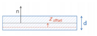
For Physical offset enter a value or expression in the zoffset field for the actual distance from the meshed boundary to the shell midsurface.
Figure 5-5: Meshed boundary indicated in red. The vector n indicates the positive orientation of the shell normal.
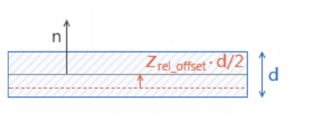
For Relative offset enter a value or expression in the zrel_offset field for the offset as the ratio between the offset distance and half the shell thickness. A value of +1 means that the actual shell bottom surface is located on the meshed boundary, and a value of -1 means that the shell top surface is located on the meshed boundary.]
Figure 5-6: Meshed boundary indicated in red. The vector n indicates the positive orientation of the shell normal.
Location in User Interface
Context Menus
Shell>Change Thickness
Plate>Change Thickness
Ribbon
Physics tab with Shell selected:
Boundaries>Shell>Change Thickness
Physics tab with Plate selected:
Domains>Plate>Change Thickness