A shell is a thin-walled structure in 3D where a simple form is assumed for the variation of the displacement through the thickness. Using this approximation, it is possible to develop a model for the deformation that is more similar to a 2D plane stress condition than to a full 3D state.
Plates are similar to shells but act in a single plane and usually with only out-of-plane loads. The plate and shell elements in COMSOL Multiphysics
are based on the same formulation. The Plate interface for 2D models is a specialization of the Shell interface. In the following, the text fully describes the Shell interface, and the Plate interface is mentioned only where there are nontrivial differences.
The dependent variables are the displacements u,
v, and
w in the global
x,
y, and
z directions, and the displacements of the shell normals
ax,
ay, and
az in the global
x,
y, and
z directions.
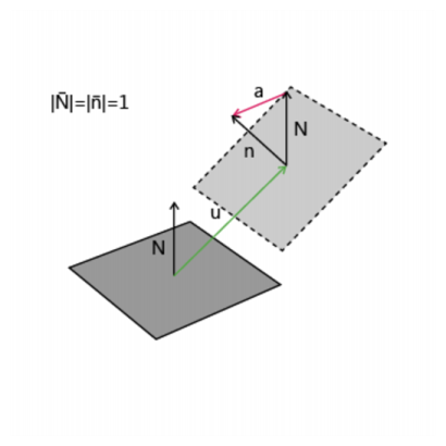
The degrees of freedom represent the displacements on the reference surface. The reference surface is the boundary where the shell element mesh is created. If an offset property is used, the reference surface differs from the physical shell midsurface. The displacement vector on the midsurface,
u, can be expressed as
where uR is the displacement on the reference surface (the displacement degrees of freedom) and
ζ0 is the offset. The rotational displacement
a is the same on both midsurface and reference surface.
For input and output, the Shell interface to a large extent replaces the displacements of the shell normals by the more customary rotations θx,
θy, and
θz about the global axes. For a geometrically linear analysis, the relation between normal displacement and rotation vector is simple:

where
n is the unit normal of the shell.
For a standard plate analysis only three degrees of freedom are needed: the out-of-plane displacement w and the displacements of the shell normals
ax and
ay. It is also possible to activate all six degrees of freedom, so that any type of analysis of a shell initially positioned in the
xy-plane can be performed using the Plate interface. Using six degrees of freedom is the default, but three degrees of freedom can be selected instead for efficiency.
Also for plates, the rotations θx,
θy (and possibly
θz) are used to a large extent.