Coupling Techniques
The following basic techniques to connect physics interfaces with displacement degrees of freedom is discussed in this section:
Renaming Degrees of Freedom
The easiest coupling method is to rename the displacement degrees of freedom so that these are the same for all physics interfaces. This is sufficient, for example, when using membranes as cladding on a solid boundary or truss elements as reinforcement bars in a solid.
In the Beam, Shell, and Plate interfaces, the deformation is described also by rotational degrees of freedom. In the general case, these degrees of freedom interact with the translational degrees of freedom in a connection.
In some special cases—for example, when a thin shell acts as cladding on a solid—it is sufficient to make the degree of freedom names for the displacements common; the rotational degrees of freedom are not important. If, however, a shell edge is connected to a solid, it acts as a ‘hinge’, which in most cases is not the intended behavior. You then need to use the more sophisticated techniques described next.
Using Customized Coupling Features
There are a number of built-in couplings, by which you can add connections that are difficult to set up manually:
Shell Edge to Solid Boundary (3D)
A shell can be coupled to a solid by adding a Solid-Shell Connection multiphysics coupling. In the settings, set Connection type to Solid boundaries to shell edges. This situation typically occurs when you want to make a transition from a thin region to one which is thicker. Usually, shell assumptions should be valid on both sides of the transition.
Shell Boundary to Solid Boundary (3D)
A shell can also be coupled to a solid by adding a Solid-Shell Connection multiphysics coupling with Connection type set to Solid and shell shared boundaries or Solid and shell parallel boundaries. This connection is used to add a shell on top of a solid as a ‘cladding’. It is possible to include an offset distance. The boundaries may be coincident or parallel.
Beam Point to Solid Boundary (2D)
A beam can be coupled to a solid by adding a Solid-Beam Connection multiphysics coupling. In the settings, set Connection type to Solid boundaries to beam points. This coupling is intended for modeling a transition from a beam to a solid where beam assumptions are valid on both sides of the connection.
Beam Edge to Solid Boundary (2D)
A beam can also be coupled to a solid by adding a Solid-Beam Connection multiphysics coupling with Connection type set to 
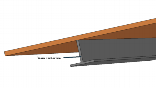
Solid and beam parallel boundaries. This connection is used for adding a beam on top of a solid as a ‘cladding’. The boundaries are assumed to be parallel.
Beam Edge to Shell Edge (3D)
A beam can be coupled to a shell by adding a Shell-Beam Connection multiphysics coupling with Connection type set to either Shell and beam shared boundaries or Shell and beam parallel boundaries. This connection is used for adding beams as stiffeners to shells. The edges may be coincident or parallel. It is possible to prescribe that the beam has an offset from the shell when a coincident edge is used.
Beam Point to Shell Boundary (3D)
A beam can be coupled to a shell by adding a Shell-Beam Connection multiphysics coupling with Connection type set to Shell boundaries to beam points. This connection is used for modeling a beam with one end ‘welded’ to the face of the shell. You can specify the size of the are around the beam end that is connected in several ways.
Beam Point to Shell Edge (3D)
A beam can be coupled to a shell by adding a Shell-Beam Connection multiphysics coupling with Connection type set to Shell edges to beam points. This connection is used for modeling a beam with one end ‘welded’ to the edge of the shell. You can specify how large portion of the edge that is connected to the beam end in several ways.
The underlying theory and more details can be found in Connection Between Shells and Solids and Connection Between Shells and Beams.
Examples of all types of couplings between shells and beams are shown in Connecting Shells and Beams: Application Library path Structural_Mechanics_Module/Tutorials/shell_beam_connection
An example of couplings between shells and solids is shown in Connecting Shells and Solids: Application Library path Structural_Mechanics_Module/Tutorials/shell_solid_connection
Using General Coupling Operators
The most general method of connecting parts modeled with different physics interfaces is by using a General Extrusion operator. In this case the parts need not even be in contact, so the connection is an abstraction.
An example could be a shell stiffened by beams. In practice, you would probably use the built-in coupling described in Beam Edge to Shell Edge (3D) for this case, but the examples displays the principles.
In structure like this, the beam is usually placed at one side of the shell, so that the centerline of the beam and the midsurface of the shell do not coincide. This difference must be taken into account, so the edges representing the beam are geometrically disconnected from the midsurface of the shell.
Mathematically, the connection between the beam and the shell can be expressed as
or equivalently as
Here φ is the rotation vector, which contains the rotational degrees of freedom in the Beam interface. The rotation vector is also available as a variable in the Shell interface, where it is derived from the rotational degrees of freedom a. The shell normal is denoted by n.
To create the coupling:
1
Add a General Extrusion node under Definitions. Select the line on the shell midsurface as source. Enter data in the Destination Map.
2
Add a Prescribed Displacement/Rotation node in the Beam interface and select the corresponding edge.
3
Enter data for the prescribed displacements and rotations, for example genext1(u)+genext1(shell.thy)*zdist, where zdist is some expression defining the distance from the beam axis to the shell midsurface.
In the COMSOL Multiphysics Reference Manual: