Releasing Polarized Rays
The default behavior of the ray release features is to treat the rays as unpolarized plane waves for the purpose of computing intensity and polarization. However, every release feature except the Solar Radiation node is capable of releasing wavefronts that are spherical or ellipsoidal in shape, with varying degrees of polarization.
Initial Radii of Curvature
In the Settings windows for release features, such as the Release, Release from Grid, and Inlet features, change the 
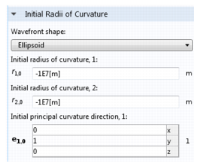
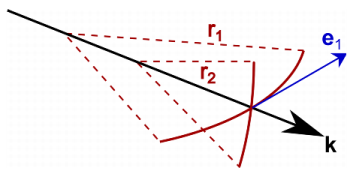
Wavefront shape setting to control the initial principal radii of curvature of the wavefront. The default setting, Plane wave, sets the initial principal radii of curvature to be approximately 
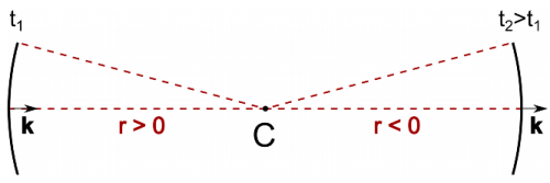
8 orders of magnitude longer than the characteristic length of the geometry. In 2D it is also possible to release cylindrical waves with user-defined principal radii of curvature. The radius of curvature may be interpreted as the distance to a point at which the ray intensity becomes infinite within the approximations of geometrical optics. This distance is considered positive if the wavefront is converging and negative if the wavefront is diverging.
Figure 2-5: Sign conventions associated with the principal radius of curvature of a cylindrical wave before and after encountering a caustic at point C.
In 3D it is possible to release spherical waves in which both principal radii of curvature are equal. The radii of curvature follow the same sign convention as that for wavefronts in 2D. It is also possible to define the Wavefront shape as an Ellipsoid for which both principal radii of curvature are initialized independently of each other. It is then necessary to define an Initial principal curvature direction e1,0.
Figure 2-6: Settings for specifying the initial radii of curvature in 3D.
The orientation of the wavefront is then defined so that the first principal curvature direction is the radius of the circular arc that is created via the intersection of the wavefront with a plane that contains the ray direction vector and the principal curvature direction vector.
Figure 2-7: Interpretation of the two principal radii of curvature and the first principal curvature direction vector in 3D models.
Initial Polarization
By default, the ray release features release unpolarized rays, but it is also possible to release rays with varying degrees of polarization.
The Stokes parameters of the ray are defined in a local coordinate system with axes parallel to the ray direction vector, the projection of the principal curvature direction vector onto a plane perpendicular to the ray direction vector, and the cross product of these two vectors.
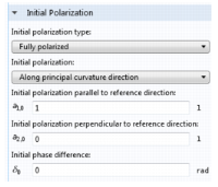
When a Fully polarized or Partially polarized ray is released, select an option from the Initial polarization list: Along principal curvature direction or User defined. For 
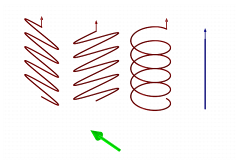
Along principal curvature direction the initial Stokes parameters is defined in the local coordinate system that is used to define the principal radii of curvature. For User defined another coordinate system may be selected, and the Stokes parameters are automatically transformed to the coordinate system defined by the principal curvature direction. It is also possible to define a phase difference between the electric field components parallel to and perpendicular to the projection of the reference direction onto the plane perpendicular to the ray direction vector, resulting in varying degrees of elliptical polarization.
Figure 2-8: Settings for specifying the initial polarization of a fully polarized ray.
Figure 2-9: Comparison of four initial polarization states. From left to right: Polarization parallel to the reference direction, polarization perpendicular to the reference direction, circular polarization, and no polarization.
Similar options are available in the settings window for the Illuminated Surface node; the initial radii of curvature and Stokes parameters are then computed from the interaction of incident rays with a surface.