PDF

From Surface Mesh to Geometry: STL Import of a Vertebra1
Introduction
The STL file format is one of the standard file formats for 3D printing, and it is also often used as a format for exchanging 3D scan data. STL files contain only the triangulated surface, which we can also call a surface mesh, of a 3D object. The triangles in the file are identified by their normals and vertex coordinates.
COMSOL Multiphysics supports the import of surface meshes from STL files. Using available tools you can partition the imported mesh and generate a solid geometry object. During the mesh-to-geometry conversion process a simplification algorithm helps with smoothing out defects in the imported mesh. You can then further modify the generated geometry using geometric operations.
Model Definition
Import the STL file of a vertebra geometry shown below.
Follow the instructions in this tutorial to
Application Library path: COMSOL_Multiphysics/Meshing_Tutorials/stl_vertebra_import
Modeling Instructions
From the File menu, choose New.
New
In the New window, click Model Wizard.
Model Wizard
1
In the Model Wizard window, click 3D.
2
Click Done.
Geometry 1
Import 1 (imp1)
1
On the Home toolbar, click Import.
2
In the Settings window for Import, locate the Import section.
3
Click Browse.
4
5
Click Import.
The import of an STL file consists of three steps: the import of the surface mesh from the file, the generation of a surface geometry from the imported mesh, and finally the creation of a solid object. After the import is complete the geometry appears on the screen. According to the information in the Messages window a solid object could be created from the mesh.
Notice that after the import completes you can no longer see the reference to the STL file in the Settings window. The source for the geometry import is now Mesh Part 1, which is where the mesh import can be found. The Import 1 node in the geometry sequence handles the last steps of the process: conversion from mesh to geometry, and creation of a solid object.
6
Click Go to Source  to locate the source mesh in the Model Builder window.
Mesh Part 1
The Mesh Part 1 sequence is added under the Global Definitions>Mesh Parts node. The output of a mesh import sequence added here can be imported into any geometry sequence in the mph file.
The meshing sequence in a Mesh Part has a length unit, just as a geometry sequence. Since STL files do not include units, the length unit is set to the default geometry length unit, meter.
1
In the Model Builder window, under Global Definitions>Mesh Parts click Mesh Part 1.
2
In the Settings window for Mesh Part, locate the Units section.
3
Select the Use units check box.
4
From the Length unit list, choose mm.
Geometry 1
Although the length unit of the Mesh Part 1 sequence now has the correct value, you also need to update the length unit of the Geometry 1 sequence. One way to avoid to update both is to set the length unit of the geometry sequence before importing the file.
1
In the Model Builder window, under Component 1 (comp1) click Geometry 1.
2
In the Settings window for Geometry, locate the Units section.
3
From the Length unit list, choose mm.
4
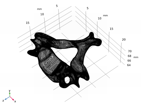
On the Home toolbar, click Build All. This will update the length unit of the Geometry 1 sequence, and re-import the geometry from the mesh.
Now modify the orientation of the geometry to improve the visualization.
Rotate 1 (rot1)
1
On the Geometry toolbar, click Transforms and choose Rotate.
2
3
In the Settings window for Rotate, locate the Rotation Angle section.
4
In the Rotation text field, type 90.
5
Locate the Axis of Rotation section. From the Axis type list, choose x-axis.
6
Click Build Selected.
7
Click the Zoom Extents button on the Graphics toolbar.
Rotate 2 (rot2)
1
On the Geometry toolbar, click Transforms and choose Rotate.
2
3
In the Settings window for Rotate, locate the Rotation Angle section.
4
In the Rotation text field, type -90.
5
Locate the Axis of Rotation section. From the Axis type list, choose z-axis.
6
Click Build Selected.
7
Click the Zoom Extents button on the Graphics toolbar.
Mesh 1
A first step to assess the quality of an imported geometry is to create a mesh. Problem regions, for example small faces or short edges, are detected and reported by the mesher.
1
In the Model Builder window, under Component 1 (comp1) click Mesh 1.
2
In the Settings window for Mesh, click Build All.
Two short edges, which are listed in the Warning 1 node that appears, have been detected.
Warning 1
1
2
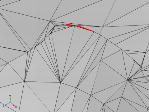
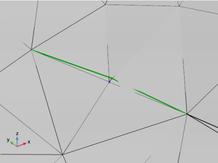
Click the Zoom to Selection button on the Graphics toolbar. If the short edge is hidden behind the mesh zoom out, rotate the geometry, then click the Zoom to Selection button again to find the area highlighted in the figure below.
The two edges are located at the boundary of a small face that forms a fold in the geometry. To find where the two short edges originate from switch to the Mesh Part 1 sequence.
Mesh Part 1
For a better overview of all boundaries on the imported mesh open the Selection List window.
1
In the Model Builder window, under Mesh Component 1 (mcomp1) click Mesh Part 1.
2
On the Home toolbar, click Windows and choose Selection List.
3
Click the Select Boundaries button on the Graphics toolbar.
4
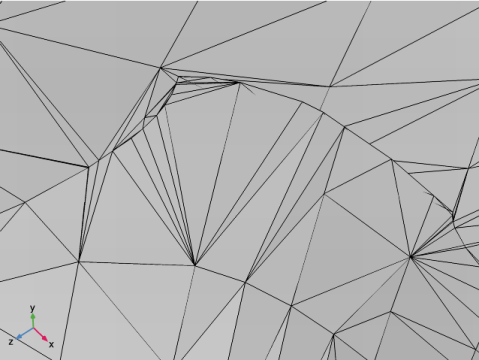
In the Settings window for Selection List, In the list, choose 3 (meshed) and 4 (meshed).  Hold down Ctrl while clicking in the list to select multiple boundaries.
5
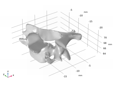
Click the Zoom to Selection button on the Graphics toolbar. If needed, zoom out and rotate the geometry before zooming in on the boundary again.
6
Click the Transparency button on the Graphics toolbar.
On the imported mesh Boundaries 4 and 5 are in the same location as the short edges on the generated geometry. These are isolated boundaries on the outside of the surface mesh, and are attached to the mesh only through a single edge. Isolated boundaries such as these are automatically removed during the last step of the geometry creation process, when the solid object is created.
In the following we will delete these boundaries from the imported mesh. First, we join all boundaries to get rid of Boundary 3 that is responsible for the small fold in the final geometry.
7
Switch to the Model Builder window.
8
On the Mesh toolbar, click Join Entities.
This adds the Joined Entities 1 operation to the Mesh Parts 1 sequence.
Join Entities 1
1
In the Model Builder window, under Mesh Component 1 (mcomp1)>Mesh Part 1 click Join Entities 1.
2
In the Settings window for Join Entities, locate the Geometric Entity Selection section.
3
From the Geometric entity level list, choose Boundary.
4
From the Selection list, choose All boundaries.
5
Click Build Selected.
According to the Warning 1 node displayed under Join Entities 1 not all selected boundaries could be joined. This is expected since the two isolated boundaries cannot be joined. Instead we will delete these.
6
On the Mesh toolbar, click Delete Entities.
Delete Entities 1
1
In the Model Builder window, under Mesh Component 1 (mcomp1)>Mesh Part 1 click Delete Entities 1.
2
In the Settings window for Delete Entities, locate the Geometric Entity Selection section.
3
From the Geometric entity level list, choose Boundary.
4
In the Settings window for Selection List, In the list, choose 2 (meshed) and 3 (meshed).
5
Click Add to Selection in the window toolbar.
6
Right-click Mesh Component 1 (mcomp1)>Mesh Part 1>Delete Entities 1 and choose Build Selected.
After the operation completes the Selection List window lists only one boundary for the mesh. The isolated boundaries are no longer there, but the small fold in the mesh is still visible.
7
Close the Selection List window.
Geometry 1
1
On the Home toolbar, click Build All.
2
In the Model Builder window, under Component 1 (comp1) click Geometry 1.
3
In the Settings window for Geometry, click Go to Default View.
4
The short edges are no longer present in the geometry. The small fold in the surface has also disappeared because this time it is part of a larger surface, and therefore it could be removed by the mesh simplification algorithm that is part of the conversion to geometry.
Mesh 1
1
In the Model Builder window, under Component 1 (comp1) click Mesh 1.
2
In the Settings window for Mesh, click Build All.
This time the mesh builds without any warnings.
Geometry 1
Import 1 (imp1)
1
In the Settings window for Import, locate the Import section.
2
In the Relative simplification tolerance text field, type 0.001.
By setting a tighter tolerance we are reducing how much the imported mesh can be modified by the mesh simplification algorithm. This tolerance is relative to the entire geometry and together with the Defect removal factor, which is relative to the local feature size, controls how much the imported mesh can be modified at a certain location before converting it to geometry. Decreasing the relative simplification tolerance should work in this case, since apart from some small local defects the imported surface mesh seems quite good.
3
Click Build All Objects.
With the smaller tolerance the processing time increases, but the generated solid object follows the imported mesh more accurately.
Block 1 (blk1)
In the following create a block and combine it with the imported vertebra geometry to create a domain outside of the vertebra, and to cut the geometry in half.
1
On the Geometry toolbar, click Block.
2
In the Settings window for Block, locate the Size and Shape section.
3
In the Width text field, type 23[mm].
4
In the Depth text field, type 15[mm].
5
In the Height text field, type 15[mm].
6
Locate the Position section. In the x text field, type -22[mm].
7
In the y text field, type -11[mm].
8
In the z text field, type 60[mm].
9
Right-click Block 1 (blk1) and choose Build Selected.
Partition Objects 1 (par1)
1
On the Geometry toolbar, click Booleans and Partitions and choose Partition Objects.
2
Select the object blk1 only (the block).
3
In the Settings window for Partition Objects, locate the Partition Objects section.
4
Find the Tool objects subsection. Select the Active toggle button.
5
Select the object rot2 only (the vertebra).
6
Click Build Selected.
7
Click the Transparency button on the Graphics toolbar.
8
Click Go to Default View.
The resulting object now contains two domains, inside and outside the imported geometry. As a final step create a mesh for the geometry.
Mesh 1
1
In the Model Builder window, under Component 1 (comp1) click Mesh 1.
2
In the Settings window for Mesh, click Build All.
 

1
The STL geometry is provided courtesy of Mark Yeoman, Continuum Blue, UK.