Use the Fluid-Film Properties node to set the wall properties, base properties, fluid properties, and the film flow model.
In the Thin-Film Flow, Shell (tffs) and
Thin-Film Flow, Edge (tffs) interfaces, the
Reference normal orientation setting allows you to reverse the direction of the reference surface normal used by the physics interface. By default this is set to
Same direction as geometry normal. To reverse the direction, select
Opposite direction to geometry normal.
In the Thin-Film Flow, Domain (tff) interface, the
Reference surface normal orientation setting allows you to set the direction of the reference normal so that it either points out of or into the plane of the domain. By default this is set to
Reference surface normal points out of plane, such that the reference surface normal is given by {0,0,1}. Selecting
Reference surface normal points into plane sets the reference surface normal to {0,0,-1}.
Enter a value or expression for the Height of wall above reference plane hw1 (SI unit: m). The default is 10
μm.
By default the Additional wall displacement is
User defined. Enter values or expressions for
uw (SI unit: m). The defaults are 0 m. Alternatively select a feature input (defined by a separate physics interface) or
None from the list.
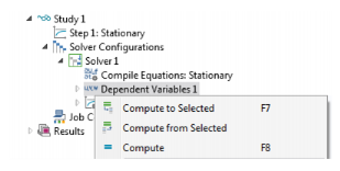
To determine the reference normal orientation before fully solving the model, click Show Default Solver (

) on the
Study toolbar (or right-click the
Study 1 node and select
Show Default Solver). Then expand the
Study 1>Solver Configurations>Solver 1 node, right-click the
Dependent variables sub-node and select
Compute to Selected.
You can then add a 2D or 3D plot group with an Arrow Surface plot (in 3D) (

) or
Arrow Line plot (in 2D) (

), and use the
Replace Expression (

) button to plot the
Reference surface normal.
Select a Wall velocity vw (SI unit: m/s) —
None (the default),
Calculate from wall displacement, or
User defined. For
User defined enter values or expressions for the components of
vw (SI unit: m/s). The defaults are 0 m/s.
See Wall Properties above for details to help you decide whether the additional displacement should be added to the wall or the base.
Enter a value or expression for the Height of base below reference plane hb1 (SI unit: m). The default is 0 m.
By default Additional base displacement is
User defined. Enter values or expressions for
ub (SI unit: m). The defaults are 0 m. Or select
None from the list.
Select a Base velocity vb (SI unit: m/s) —
None (the default),
Calculate from base displacement, or
User defined. For
User defined enter values or expressions for the components of
vb (SI unit: m/s). The defaults are 0 m/s.
The default Dynamic viscosity μ (SI unit: Pa·s) is taken
From material. For
User defined enter a different value or expression. The default is 0 Pa·s.
With the default options, the Density ρ (SI unit: kg/m
3) is taken
From material. For
User defined enter a different value or expression. The default is 0 kg/m
3. If the
Modified Reynolds Equation is being solved, the density is determined automatically by the ideal gas law. If cavitation is enabled, the density is assumed to take the form
ρ=
ρc exp(
βpf) where
pf is the fluid pressure,
ρc is the density at the cavitation pressure, and
β is the compressibility. (SI unit: 1/Pa). In this case enter the values for the
Density at cavitation pressure ρc (SI unit: Pa) and the
Compressibility β (SI unit: 1/Pa).
Select a Film flow model —
No-slip walls (the default),
Slip at walls,
User defined-relative flow function, or
User defined-general. The film flow model is used to compute the mean fluid velocity as a function of the pressure gradient, the wall velocity, and the base velocity. Within the gap the fluid velocity profile is a linear combination of the Poiseuille and Couette velocity profiles.
Use Slip at walls when slip occurs at the wall and/or the base. In this case the difference between the wall or base velocity and the fluid velocity is proportional to the tangential part of the of the normal stress tensor component. The slip length divided by the fluid viscosity is the constant of proportionality in this relationship. The mean fluid velocity is computed using this assumption, given the pressure gradient and the wall and base velocities.
Enter a Slip length, wall Lsw (SI unit: m). The default is 0.1
μm. Select the
Use different slip length for base check box to enter a
Slip length, base Lsb (SI unit: m). The default is 0.1
μm.
For the Modified Reynolds Equation it is possible to use the gas mean free path to specify the slip length. Change the
Type of Slip setting (which defaults to
Slip Length with the settings described above) to
Mean free path and same accommodation coefficients or to
Mean free path and different accommodation coefficients.
|
•
|
For Mean free path and same accommodation coefficients enter a value for the Wall and base accommodation coefficient α (dimensionless). The default is 0.9.
|
|
•
|
For Mean free path and different accommodation coefficients enter values for the Wall accommodation coefficient αw (dimensionless, default 0.9) and the Base accommodation coefficient αb (dimensionless, default 0.9).
|
Select an option to define the Mean free path—
Compute from material properties (the default),
User defined expression, or
User defined with reference pressure.
|
•
|
For User defined expression enter an expression for the Mean free path λ (SI unit: m). The default expression is ((70[nm])´(1[atm]))/(tffs.ptot).
|
|
•
|
For User defined with reference pressure enter values for the Mean free path at reference pressure λ0 (SI unit: m; the default is 70 nm), and for the Mean free path reference pressure pλ0 (SI unit: Pa; the default is 1 atm).
|
The Rarefied-total accommodation option provides a rarefied gas model that assumes total accommodation at the wall and the base. This model is accurate to within 5% over the range 0
<Kn<880 (here
Kn is the Knudsen number, which is the ratio of the film thickness to the mean free path). An empirical function, fitted to stationary solutions of the Boltzmann equation, is used to define the Poiseuille component of the flow.
Select an option to define the Mean free path—
Compute from material properties (the default),
User defined expression, or
User defined with reference pressure.
|
•
|
For User defined expression enter an expression for the Mean free path λ (SI unit: m). The default expression is ((70[nm])´(1[atm]))/(tffs.ptot).
|
|
•
|
For User defined with reference pressure enter values for the Mean free path at reference pressure λ0 (SI unit: m; the default is 70 nm) and for the Mean free path reference pressure pλ0 (SI unit: Pa; the default is 1 atm).
|
Select a Force model. Select:
The Rarefied-general accommodation option provides a rarefied gas model that assumes the same accommodation coefficient,
α, at the wall and the base. This model is accurate to within 1% over the ranges 0.7
<α<1 and 0.01
<Kn<100 (here
Kn is the Knudsen number, which is the ratio of the film thickness to the mean free path). An empirical function, fitted to stationary solutions of the Boltzmann equation, is used to define the Poiseuille component of the flow.
Select an option to define the Mean free path—
Compute from material properties (the default),
User defined expression, or
User defined with reference pressure.
|
•
|
For User defined expression enter an expression for the Mean free path λ (SI unit: m). The default expression is 70[nm]*1[atm]/tffs.ptot.
|
|
•
|
For User defined with reference pressure enter values for the Mean free path at reference pressure λ0 (SI unit: m, the default is 70 nm) and for the Mean free path reference pressure pλ0 (SI unit: Pa, the default is 1 atm).
|
Select a Force model. Select:
The User defined-relative flow function option enables user-defined models in which an effective fluid viscosity is employed. The fluid viscosity is divided by an additional factor
Qch, which can be defined as an arbitrary expression in the GUI. It is also possible to define the expressions for the fluid forces on the wall and on the base (these are included as feature inputs in other physics interfaces).
The User defined-general option allows for arbitrary flow models to be defined. Both the Poiseuille and Couette terms in the mean velocity can be defined arbitrarily. It is also possible to define the expressions for the fluid forces on the wall and on the base, (these are included as feature inputs in other physics interfaces).