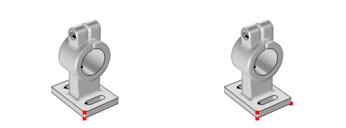
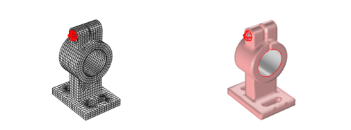
The following overview is based on using an imported mesh from the feeder_clamp model, found in the COMSOL Multiphysics Applications Libraries and shown in
Figure 8-4.
To form a single domain, use a Join Entities (

) node, which operates on the domain level (that is, add
All domains to the selection). As a result, you can obtain a mesh for the model with a single domain.
To remove all edges, use a Delete Entities (

) node, which operates on the edge level (that is, add
All edges to the selection). As a result, you can obtain a mesh for the model with no edges or points.
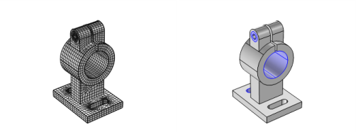
To define a boundary that defines the contact between the feeder and the clamp, use a Cylinder (

) node that operates on the boundary level (that is, add
All boundaries to the selection, and use
10.001 as a cylinder radius,
0 and
-20 for top and bottom,
(15, 0, 35) as position, and
y-axis as the axis type).
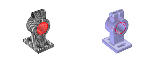
To define two boundaries that define screw channels, use a Logical Expression (

) node, which operates on the boundary level (that is, add
All boundaries to the selection and use
(y+10)^2+(z-55)^2<=4 as the expression).
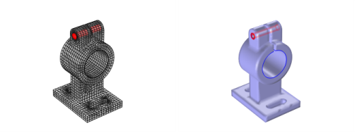
To create a boundary defining one of the washers used for the boundary loads of the model, use a Ball (

) node, which operates on the boundary level (use
(5,-10, 55) as a ball center and 3.5 as a ball radius). The input boundary selection must be limited; otherwise, the ball operation also splits one of the cylinder boundaries, which was created by the
Logical Expression node.
By creating a duplicate of the Ball node and modifying the ball center (set
x to
5) you can create a boundary for the second washer.
To create the boundaries for the mounting holes, use a Box (

) node, which operates on the boundary level (use
(0 - 30, -30 - 10, 0.1 - 4.9) as box limits and use the
Some vertex condition).
Using the Create Vertex (

) node, it is possible to add an additional vertex in a specified location (use
(30,-30, 0) as vertex coordinates as in
Figure 8-10).