An identity pair (
Identity Boundary Pair (

)) is a pair that, by default, makes the fields across two connected boundaries (one from each connecting object in an assembly) continuous. This is equivalent to the continuity that is obtained by default on interior boundaries in a geometry created by forming a union. Some physics provide special boundary conditions for identity pairs to model “slit conditions” such as resistive layers. You can specify boundary conditions for these pairs from the
Pairs submenu at the bottom of the boundary condition part of the context menu for the physics feature node. The nodes in the
Model Builder that represent pair boundary conditions use an icon with a pair symbol in the lower-left corner:

. There are also similar
Identity Edge Pair (

) and
Identity Point Pair (

) pair nodes.
A contact pair (

) is a pair that define boundaries where the parts can come into contact but cannot penetrate each other under deformation for modeling of structural contact and multiphysics contact.
For pairs where parts of the boundaries do not overlap you need to specify boundary conditions for the non-overlapping parts, which typically represent exterior boundaries outside of the overlapping area. These boundary conditions (fallback boundary conditions) appear as subnodes to the pair’s boundary condition node in the
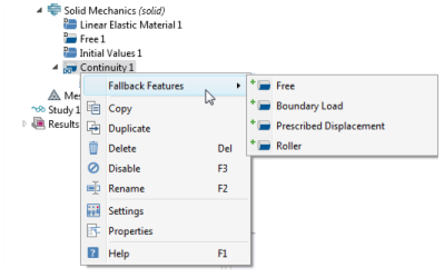
Model Builder. By default, the default boundary condition for exterior boundaries is added to the non-overlapping parts. If you want to use another boundary condition for any of the non-overlapping parts, right-click the pair’s boundary condition node (
Continuity, for example) and select any of the standard boundary conditions from the
Fallback Features submenu. In the
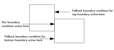
Settings window, the selection includes all applicable boundaries by default, but a separate boundary condition can be added for only a subset of the pair boundaries. In the following illustration, which shows a simple example with two partially overlapping rectangles, there is one identity pair that consists of two boundaries, each with a non-overlapping part. You can right-click the pair’s boundary condition node and, from the
Fallback Features submenu, add one fallback boundary condition for the top boundary and another fallback boundary condition for the bottom boundary if desired.