The Electrode Surface node defines an electrode surface located on an external boundary to a
Transport Properties (electrolyte) domain. The node will set up a flux boundary condition, based on electrode reaction current densities and stoichiometric coefficients according to Faraday’s law of electrolysis.
By default, an Electrode Reaction subnode is added to the feature and an arbitrary number of these subnodes can be added, which contribute to the total flux over the boundary. You may also add a
Double Layer Capacitance subnode.
The overpotential used by the Electrode Reaction subnode is based on the electric potential of the
Electrode Surface, the electrolyte potential and the individual equilibrium potentials of the
Electrode Reaction subnodes.
Use the Boundary Condition section to control the electric potential. The electrolyte potential is set to 0 by default. To use another value, enable
Migration Electric Field on the
Electrolanalysis topnode, and set the value on the
Transport Properties node. The
Film Resistance section can also contribute to the overpotentials.
Specify either a Surface resistance Rfilm (SI unit:
Ω·m
2) directly or choose the
Thickness and conductivity option to calculate the surface resistivity based on a depositing film thickness.
The perturbation parameter is either Electric potential,
Electrode potential,
Total current or
Average current density, based on the
Boundary condition selected in the next section.
Electric potential,
Electrode potential and Cyclic voltammetry will set the potential value directly, whereas
Total current,
Average current density or
Counter electrode all add an extra global degree of freedom for the potential in the electrode phase, set to comply with the chosen condition.
The Counter electrode option will set a potential to ensure an overall charge balance of the cell so that the integral of all electrode reaction currents of all electrode surface node sums up to zero.
When using the Total current option in 1D or 2D, the boundary area is based either on the
Cross sectional area (1D), or the
Out-of-Plane thickness (2D) properties, set on the physics interface top node.
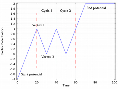
The Cyclic voltammetry setting varies the electric potential linearly in time as follows when used in conjunction with a
Cyclic Voltammetry study step:
More advanced waveforms can be obtained using the Electric potential option with a parameter setting based on
Functions found in the
Definitions menu.
If Cyclic voltammetry is selected as the
Boundary condition, the
Smoothing of cyclic voltammetry wave functions check box is selected by default and the
Smoothing factor defaults to 1·10
-3. When enabled, smoothing is applied on the triangular wave around the vertex potentials. The smoothing zone corresponds to the product of the smoothing factor with half the duration of one period of the triangular wave. .